NOTE: Spare tires originally mounted under the bed will have to be removed.
INSTRUCTIONS
1. Remove the bed from the truck.
2. Remove the spare tire.
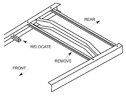
3. Remove the forward spare tire mounting crossmember. The
crossmember is located behind the shock mounts and bolted to the top of the frame.
4. The bracket that supports the rear brake line where the rear brake hose starts will have
to be relocated. Remove the rivet taking care to avoid damaging the bracket, brake line,
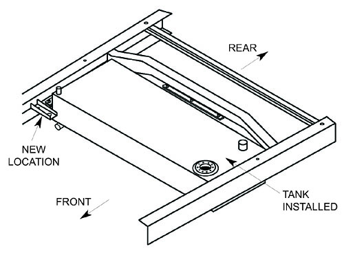
or the brake hose. The bracket will be reinstalled 3” forward of its original location after the fuel tank has been mounted.
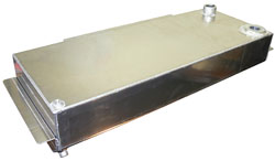
5. Position the fuel tank under the rear of the truck between the rear crossmember and the rear axle. The fuel filler should be located to the left rear corner of the bed.
6. Using a floor jack against the bottom of the fuel tank, hold the fuel tank mounting flange tight against the bottom of the frame.
7. Using the flange backing strip as a template mark and drill 3 3/8” holes thru the bottom of the frame and the tank mounting flange on each side and the rear of the fuel tank.
8. Position the flange backing strip in the channel of the frame as shown in the diagram below.
9. Bolt the fuel tank in place using the nine 3/8 bolts, flat washers, and lock washers supplied with the kit.
10. Lower and remove the floor jack that was holding the fuel tank in place.
11. Position the brake line bracket 3” forward of its original location. Drill a 3/8 hole thru the frame and bolt the bracket onto the frame using the rivet hole in the bracket. It may be necessary to loosen the brake line retaining clips and “massage” the brake line to take up any slack.
12. Thread a fitting in to the bung located on the top of the fuel tank. Connect a vent hose to the fitting. (Make sure that the vent
hose is safe for use with gasoline) The other end of the vent hose should be located 18” above the gas cap.
13. Be sure to read and follow the instructions that came with the sending unit. Check that the resistance of the sending unit is correct for the fuel gauge. Install the fuel tank sending unit thru the flange on top of the fuel tank. Align the top of the sending unit mounting holes with the threaded holes in the sending unit flange on the top of the fuel tank making certain that the float can not contact the sides of the fuel tank or the inner baffles. Tighten the sending unit with the 5 10-32 screws supplied with the sending unit.
Parts List:
1 ea 1947-54 Fuel Tank
13 ea 3/8-16 x 1 grade 8 bolt
13 ea 3/8 Lock Washer
13 ea 3/8 Flat Washer
6 ea Flange Backing Strip
1 ea Gas Cap (trap door style tank only)
Required Parts:
Fuel Line
Hose Clamps
1/2” Vent hose
Fuel Level Sending Unit
Fuel Line Fittings


