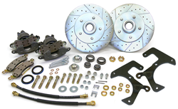
Part #WBK5.5-5764
Read these instructions completely before installing this kit!!!
NOTE: Before beginning installation, TAKE THE FRONT WHEELS THAT YOU ARE GOING TO USE AND MAKE SURE THAT THEY FIT THE ROTOR BOLT PATTERN, AND THAT THEY HAVE A LARGE ENOUGH CENTER HOLE. THESE ARE 11 3/4” ROTORS SO YOU’LL NEED 15” WHEELS. Note also that this kit will move the front wheels in approximately 1/2” on each side.
Make sure this kit fits your application before painting or plating. Parts that have been painted, plated or modified may not be returned.
This Conversion Kit uses the following components:
Rotors:
- 73-93 F100/F150 2wd
- 75-93 E100/E150 2wd
Calipers: (includes pads, anti-rattle clips, mounting bolts)
71-76 CHEVROLET – IMPALA, BELAIR, BISCAYNE
BUICK – ELECTRA, LESABRE, ROADMASTER, WILDCAT, ESTATE WAGON, PARK AVE, CENTURION
PONTIAC – BONNEVILLE, CATALINA
OLDSMOBILE – 88, 98, DELTA 88, REGENCY 98
Bearings & seals:
- OUTER – A2/SET 2 USED ON 64-77 GM INTERMEDIATE CARS
- CAMARO, FIREBIRD, CHEVELLE, MONTE CARLO, ETC.
- INNER – A13/SET 13 STANDARD INNER BEARING USED IN FORD ROTOR.
- SEAL – NATIONAL 44053 – STANDARD SEAL USED oN 57-64 FORD 1/2 ton pickup.
- Remove the stock Ford drums and backing plates. Retain the stock wheel bearing nut and washer for re-use later on. Clean spindle bearing surfaces and seal diameter.
- Check and see if the nut on the king pin lock is on the rear side of the axle. If it is, remove the nut and lockwasher from the king pin lock. Now remove the king pin lock with a hammer and punch. Re-install the king pin lock from the rear and re-install the nut and lock washer. Make sure you don’t move the spindle while you are doing this or you may move the notch in the king pin out of position.
- Install the caliper mounting bracket on the back (engine) side of the spindle with the caliper opening towards the rear of the vehicle. Note that there is a L/H and R/H bracket as marked on each bracket. Also note that the tab welded onto the bracket at the lower rear hole has a notch in it, this is for clearance on the stock steering arm. Make sure that the tab is flat against the steering arm before installing the bolt in this hole. Install the bracket at the top holes using two of the 1/2 – 20 x 2” bolts, spacers, and locknuts provided in the kit. Note that the spacers go between the bracket and the spindle. The nuts may be inside the rotor if desired. Attach the bracket at the bottom using one of the 1/2 – 20 x 2 3/4” bolts and locknuts provided. Install one of the 1/2 -20 x 2 1/2” bolts and locknuts in the forward steering arm hole. Note that the heads of these bolts must be positioned inside the rotor. This is very important! Make sure to do it right!
- Before proceeding further take the caliper for the side you are working on (bleeder up) and slide it into the bracket. Note that the caliper bracket fits between the inner pad and the caliper mounting ears. You’ll notice that it will not go all the way in because of the bump on the casting next to the piston bore. Grind off the bump using a bench grinder until it is removed flush with the housing. You’ll need to remove about 3/4” off the length of the boss. Make sure that you plug the hose bolt inlet before you start grinding. Clean the grinding dust off the caliper when your done.
- Remount the caliper and install the mounting bolts. You’ll need a 3/8” allen key for the bolts. Now turn the spindle full travel right and left and check for clearance on the axle, steering linkage and suspension, etc. Make sure you have adequate steering travel. If all is well remove the caliper assembly from the bracket.
- Remove the stock Ford truck outer bearing race from the rotor with a suitable punch and a hammer, being very careful not to damage the bore in the rotor. Install the new race from the A2 outer bearing using a bearing race installation tool – Not a hammer and punch!
- Before you grease the bearings and install the seal, mount the rotor onto the spindle with the bearings in place. Install the wheel bearing nut and washer to hold the rotor in place. Finger tight will do for now. Re-install the caliper and check for clearance one more time. You might want to mount your wheel and tire with a couple of lug nuts and make sure all is still well.
- If everything is okay, remove the caliper and rotor. Grease the bearings well (lots of good clean bearing grease), install the seal in the rotor and re-mount the rotor onto the spindle. Install the wheel bearing washer and nut and adjust. Install a new cotter pin and the dust cover that Ford used on the F100 rotor.
- Install the caliper with the bleeder up and tighten the bolts. Use a hose of your choice and a 7/16 – 20 banjo bolt. Check that the bolt is not long enough to hit the piston when you tighten it! Don’t forget the copper washers on both sides of the hose banjo.
- Do the other side the same way.


Does your 57-64 Ford 1/2 ton pickup, 5 1/2” bolt circle, Disc brake conversion kit fit 64 econolines? Looking to end up with 5×5.5 bolt pattern
Not sure as we dont see many Econolines around here. A picture of the spindle assembly would definitely help determine if it could work.
I already have your 57-64 front disc brake conversion kit on my 57. Is there a way to change rotors to the 5×4.5 or 5×4.75 bolt pattern? I believe there are many people who want to do this modification.
Hello, Our 1957-64 Ford F100 disc conversion kits are sold with the 5 X 5.5″ bolt pattern only. Unfortunately we do not sell them with the 5 X 4.75″ or the 5 X 4.5″ bolt pattern. Thank you.