Part #WBKS4954 and #WBKS5362
Read these instructions completely before installing this kit!!!
Before beginning installation, make sure your wheels fit on the disc rotor.
Make sure this kit fits your application before painting or plating. Parts that have been painted, plated or modified may not be returned.
This Conversion Kit uses the following General Motors rotors and calipers:
BUICK APOLLO, 76-77 OLDSMOBILE CUTLASS, 73-76
BUICK SKYLARK, 73-76 OLDSMOBILE OMEGA, 75-77
BUICK REGAL, 77 PONTIAC FIREBIRD, 70-77
CADILLAC SEVILLE, 75-77 PONTIAC GRAND PRIX, 73-77
CHEVROLET CAMARO, 70-77 CHEVROLET EL CAMINO, 71-77
CHEVROLET CHEVELLE, 73-76 GMC SPRINT, 71-77
CHEVROLET MONTE CARLO, 73-77
CHEVROLET NOVA, 77
NOTE: The calipers supplied with our complete kit are 1978-1981 Camaro/Firebird. They use a 10mm banjo bolt.
This is only a partial listing of applicable GM models. Ask your local parts person if your not sure. They are Raybestos #4059/#4060 (right and left respectively thru 76) and #4113/#4114 for 77.
- Remove early Chevy drums, brakes and backing plates from spindles. Make sure you retain the bearing nut and keyed washer.
- Thoroughly clean grease and dirt from spindle. Check for cracks or damage.
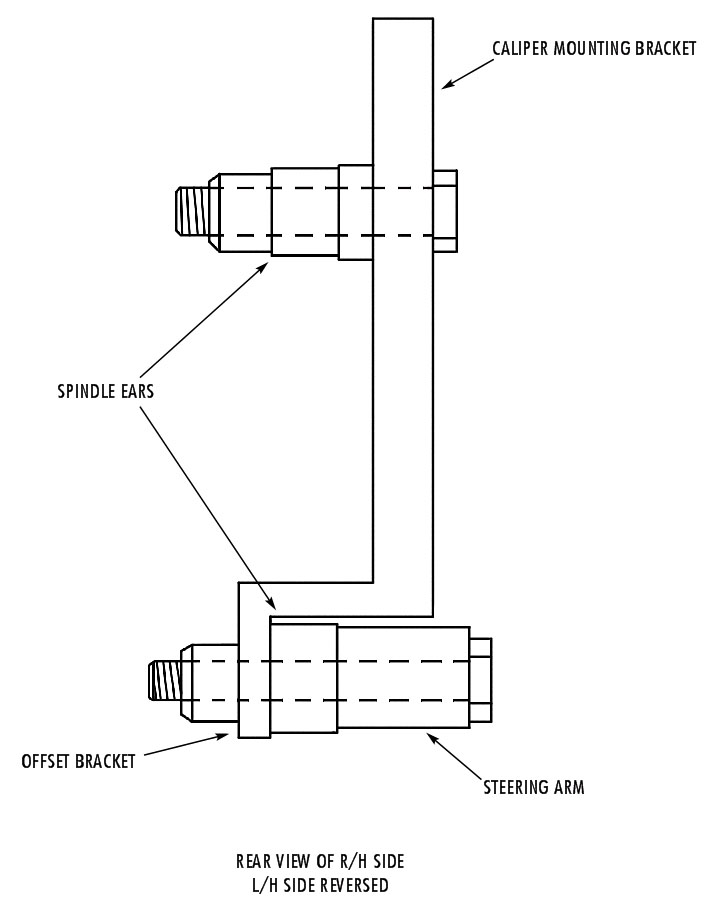
- Using one of the original bolts in the forward hole re-install the steering arm in its stock location on the spindle. Using the hardware supplied in the kit install the caliper mounting bracket on the rear of the spindle as shown in the figure. Insert the 1/4” thick round spacers between the bracket and the spindle. Check for adequate clearance between the bracket and spindle. Trim bracket if necessary.
- Examine the inner wheel bearing seating area on the spindle for nicks, etc. Emery cloth area as required for a smooth surface.
- Slide bearing adapter on spindle and drive into place using a hammer and a piece of tubing or pipe of suitable dimensions (1 1/2” pipe works great). DO NOT DAMAGE THE ADAPTER WHILE INSTALLING (use a rag for padding between tool and adapter). Drive adapter on until it seats firmly against spindle inner bearing shoulder.
- Remove bearings and inner seal from GM rotor. Remove GM inner bearing race and replace both the race and inner bearing assembly with that from a 71-80 Pinto or 70-78 Mustang. This is a widely used Ford inner wheel bearing that is readily available. It is also known as an A-13 inner bearing and consists of a L68149 cone and a L68110 race. Install a standard GM inner seal (national #8871).
- Install rotor on spindle making sure that inner bearing seats all the way onto bearing adapter. NOTE: Bearings and adapter are machined to a + .0005” tolerance. If bearing does not slide onto adapter easily it may be due to tolerance “stack-up”. This can be rectified by a small amount of fine emery “paper-work” on the bearing seating surface of the adapter.
- Install GM outer wheel bearing followed by the 3/4” I.D. x 1/4” spacer (supplied in kit) and then the stock Chevy keyed bearing retaining washer and retaining nut. Adjust bearings as required and install cotter key and bearing dust cover.
- Clean and inspect caliper for damage, leaks, etc. Install caliper on mounting bracket WITH BLEEDER FITTING UP using stock GM mounting bolts. Make sure the bolts aren’t bent or damaged before installing.
- Fill the brake system with the correct fluid, bleed and inspect for leaks.
- Check for any brake caliper/rotor/wheel interference.
- A proportioning valve may be required.*
*NOTE: In order to provide correct front to rear braking balance we suggest using a dual reservoir disc/drum type master cylinder compatible with the vehicle from which the front brakes were obtained.
*Will set wheels out 3/4” on each side.
A WORD TO THE WISE
You now have a front braking system far superior to the original installation. Because of this, it is strongly advised that the front end supporting and locating system be adequate to absorb the increased braking loads. Since normal braking action may tend to spread the forward edges of the front tires apart it is essential that you check for bent tie rods at suitable intervals. This “spreading” of the front wheels results in a compressive type of loading onto the tie rod and any “built in” bend may cause tie rod failure under severe braking.


I have a printout of a kit from you for a 1952 chevy for $375.00 that looks
like it has bearings and all parts necessary? The kit I am looking at now says
you have to put ford bearings in chevy rotors,are they included in that kit?
Is there any machine work needed on spindles for these kits?
Yes, you must install the supplied inner bearing race in order for the kit to fit properly. There should not be any special machine work required!
am interested in disc braking system do you have prices for 52 chev sedan need postage/shipping to australia.
cheers.
Sorry for the delay. This is not the area pricing and shipping question should be asked. Please
contact us at info@performanceonline.com
Thank you
Way cool! Some very valid points! I appreciate you writing this article and also the rest of the site is also really good.
Hello, I purchased this disk brake kit and had some questions. Why do you have to run the ford inner bearing and race? and are the barring and race included in this kit?
You must run the A-13 inner bearing and race as the standard bearing that fits the 70-78 Camaro rotor we use does not fit the spindle. It is too small. The race must be changed to accommodate
the bearing. Hope this makes sense.
I purchased the CBKD5557 drop spindle brake kit w/ dual diphragm. Can I use the original front brake lines & junction blocks ?
You will have to modify the brake lines to work with the dual system. We offer a front brake line conversion for this. It is available for manual or power disc brakes.
Go to this link :https://www.performanceonline.com/1955-57-CHEVY-BELAIR-DISC-BRAKE-CONVERSION-BRAKE-LINE-KIT-PRE-BENT-18371/